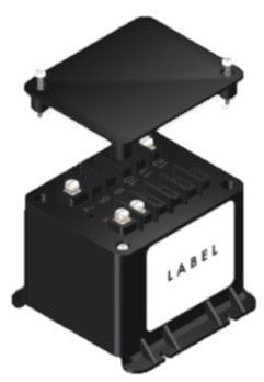
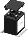
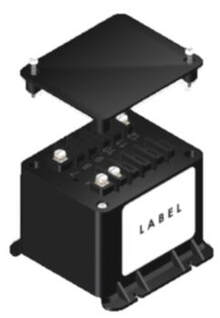
The Model CTD (Capacitor Trip Devices) manufactured by Electromagnetic Industries are designed to provide a source of energy for a circuit breaker or switch to trip during a loss of normal AC or DC power.
These devices are protected against inadvertent short circuits, input from line surges and inductive kickback from trip coils. The nominal 120Volts AC or 240VoltsAC (or DC voltage)is applied between “AC” and ‘COM” terminals. This voltage is half wave rectified and applied across the trip capacitor to give the output trip voltage. The charge stored in the capacitor is available between “ ” and “COM” terminals for the trip coil operation. The half wave rectification circuitry provides the advantage of maintaining a common neutral connection from the input and output while still maintaining the charge in the trip capacitor after a loss of control power.
The capacitor is continuously charged when control power is applied. This provides energy for normal trip coil operation. Because mechanical relays are not used, energy from the trip coil operation is immediately available with the loss of control power. When the control power returns, the capacitor will recharge and will be able to supply energy for the next trip coil operation.
CTD-1 (120V 330uF)

Max. Input Voltage 140 Vac, 125 Vdc (Surge Protected)
Capacitance 330uF, +/- 20% @25 Deg. C
Available Energy* 4.72 joules, +/- 20% @25 Deg. C
Short Circuit Protection Continuous
Normal Output Voltage* 170Vdc (w/ 120 Vac Input)
125Vdc (w/ 125 Vdc Input)
Capacitance 330uF, +/- 20% @25 Deg. C
Available Energy* 4.72 joules, +/- 20% @25 Deg. C
Short Circuit Protection Continuous
Normal Output Voltage* 170Vdc (w/ 120 Vac Input)
125Vdc (w/ 125 Vdc Input)
CTD-2 (120V 1500uF)
Max. Input Voltage 140 Vac, 125 Vdc (Surge Protected)
Capacitance 1500uF, +/- 20% @25 Deg. C
Available Energy* 21.5 joules, +/- 20% @25 Deg. C
Short Circuit Protection Continuous
Normal Output Voltage* 170Vdc (w/ 120 Vac Input)
125Vdc (w/ 125 Vdc Input)
Capacitance 1500uF, +/- 20% @25 Deg. C
Available Energy* 21.5 joules, +/- 20% @25 Deg. C
Short Circuit Protection Continuous
Normal Output Voltage* 170Vdc (w/ 120 Vac Input)
125Vdc (w/ 125 Vdc Input)
CTD-3 (240V 330uF)

Normal Input Voltage 240 VAC
Max. Input Voltage 280 VAC
Capacitance 330uF, +/- 20% @25 Deg. C
Available Energy 19 joules, +/- 20% @25 Deg. C
Temp. influence on Capacitor (-10% at -30 Deg. C., +5% at 60 Deg. C.)
Short Circuit Protection Continuous
Normal Output Voltage 338 VDC
Max. Input Voltage 280 VAC
Capacitance 330uF, +/- 20% @25 Deg. C
Available Energy 19 joules, +/- 20% @25 Deg. C
Temp. influence on Capacitor (-10% at -30 Deg. C., +5% at 60 Deg. C.)
Short Circuit Protection Continuous
Normal Output Voltage 338 VDC
CTD-4-120 & CTD-4-240
CTD-5-120 & CTD-5-240